
|
|
|
|
|
PTC
Thermistors: Definition & Function
|
|
|
Thermistors are temperature dependent resistors and "PTC"
stands for Positive Temperature Coefficient of resistance. Ceramic PTC thermistor exhibits a highly positive temperature coefficient (Figure 1) where its resistance increases rapidly past a reference temperature (or Curie temperature). The PTC thermistors we produce are based on doped semi- conductive BaTiO3 ceramics. |
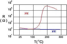 FIGURE 1:PTC and NTC thermistor resistance-temperature (R/T) profiles |
| In general, applications using PTC thermistor can be categorized according to three unique behaviors: resistance-temperature (R/T), current-voltage (I/V), and current-time (I-t) behaviors. Table 1 gives generalized plots describing these behaviors and their related applications. In many cases, all three behaviors are considered during the design phase. |
|
|
|
Typical
Plots
|
Function
|
Applications
|
||||||||||||||||
 |
R/T
|
|
||||||||||||||||
 |
I/V
|
|||||||||||||||||
 |
I/t
|
| Key points to consider when using PTC thermistors : | |
|
|
PTC performance is a function of heat dissipation conditions, thermistor dimension, Curie temperature,
thermistor resistance, applied voltage, etc. |
|
|
PTC thermistor auto-regulates its electrical power in response to thermal dissipations (e.g. a general cooling
will "prompt" thermistors to consume more electrical power to maintain its preset temperature). |
|
|
| Advantages of PTC thermistor : | |
|
|
Insensitivity to voltage fluctuations. |
|
|
Broad operating voltage range (3V to 230V). |
|
|
No controls for temperature or power needed. |
|
|
Self-setting after recovery from faults. |
|
|
Extended electrical & thermal stability Does not glow when energized (no oxygen consumption). |
|
|
Poses no fire hazards. |
|
|
Suitable for wide range of applications. |
| ABBREVIATED LETTER CODES | ||||||||||||||||||||||||||||||||||||||||||||||||||||||
|
|
|
|
|